Vehicle communication interface

One interface.
Multiple possibilities.

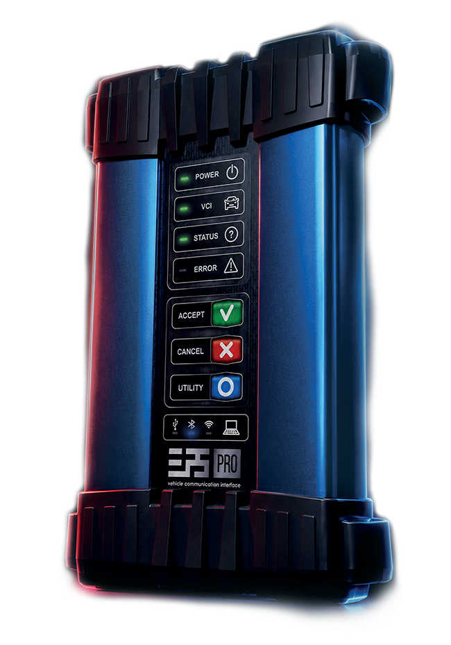
ELP5 PRO-VCI is a state-of-the-art interface. It provides reliable communication between your PC or Android-based device and the vehicle,supporting advanced diagnostics, programming, coding, flashing and service functions.

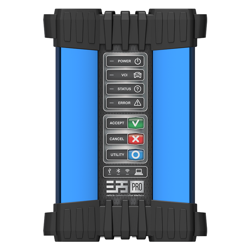
ELP5 PRO-VCI vehicle communication interface
CHANNELS
3x CAN
UP TO 5 MBPS
CAN FD
ISO 13400
DoIP
Pass-Thru
J2534

One clear workflow

Between OEM software
and the vehicle.

ELP5 PRO-VCI works as a stable communication gateway between the manufacturer's application and the vehicle control units.

  1. 01 PC with OEM software OEM application communicates through the installed J2534 driver
  2. 02 ELP5 PRO-VCI Professional vehicle communication interface
  3. 03 Vehicle & ECUs Communication through the diagnostic connector

Hardware & communication

Key features of
ELP5 PRO-VCI.

Interfaces, host connectivity and supported vehicle protocols.

01
Interface

Hardware & system

Hardware

  • 3× CANIndependent channels
  • 3× UARTIndependent serial channels
  • J1850VPW / PWM communication channel
  • Expansion slotSupport for future and custom standards

Programmable system

  • 9× I/OInput, output and bidirectional pins
  • Flexible configurationPull-up, pull-down, open-drain and Schmitt trigger
02
Host

Connectivity

Wi-Fi2.4 / 5 GHzDual-band wireless connection
Bluetooth4.2 EDRStable device connection
USB2.0 High-SpeedFast wired communication
03
Vehicle networks

Protocols

CAN / diagnostics

ISO 11898 CAN-FD 5 Mbps · ISO 11898-3 · ISO 15765 · ISO 13400 DoIP · ISO 14230 KWP2000 · ISO 14229 UDS · ISO 9141 K & L Lines

SAE

J2411 Single Wire CAN · J2818 KWP1281 · J2819 TP2.0 · J2284 High-Speed CAN · J2740 GM UART

SAE / OEM

J1850 VPW/PWM · J2610 Chrysler SCI · J2809 Honda DIAG-H · Chrysler CCD

Technical construction

Rugged outside.
Purposeful inside.

A protected housing, clearly separated connection zones and a front control panel designed for workshop use.

Top
DC input and OBDII system connector
Front
Status LEDs and control buttons
Bottom
USB-C host connector
Housing
Rubber bumpers and rubber strap
Dimensions
210 × 147 × 45 mm
Technical diagram of ELP5 PRO-VCI showing connectors, control panel and dimensions
ELP5 PRO-VCI — connector layout and overall dimensions

Technical data

Built on a
solid hardware base.

Essential product parameters collected in one readable view.

STANDARD SAE J2534-1; J2534-2 (partial) OPERATING MODES Pass-Thru / Standalone with DiagProg® on Android
CAN CHANNELS 3 independent UART CHANNELS 3 independent
CAN FD Up to 5 Mbps J1850 1 channel
HOST CONNECTION Wi-Fi 2.4/5 GHz, Wi-Fi Direct, Bluetooth 4.2 EDR, USB 2.0 High-Speed (USB-C) SYSTEM CONNECTOR System connector
PROCESSOR 1.0 GHz ARM Cortex-A9 MEMORY 1 GB DDR3 SDRAM, 1600 Mbps
CUSTOM INTERFACE 9 programmable I/O pins; SPI, UART, I²C, 1-Wire, JTAG, BDM OPERATING VOLTAGE 2.4 V – 5 V
SUPPLY VOLTAGE 8–18 V DC POWER SOURCE Vehicle DLC or external jack connector
PROTECTION ESD, overvoltage protection up to 30 V DC, overcurrent/overload protection MONITORING Power supply input/output current monitoring
HOUSING Anodized aluminium, EPDM rubber bumpers, elastic strap EXPANSION Slot for expansion board
DIMENSIONS 210 × 147 × 45 mm WEIGHT 0.68 kg

Package contents

Everything you need
to get connected.

A practical workshop set with the interface, connection cables, power adapter and transport case.

  1. 01

    ELP5 PRO-VCI

    Vehicle communication interface

  2. 02

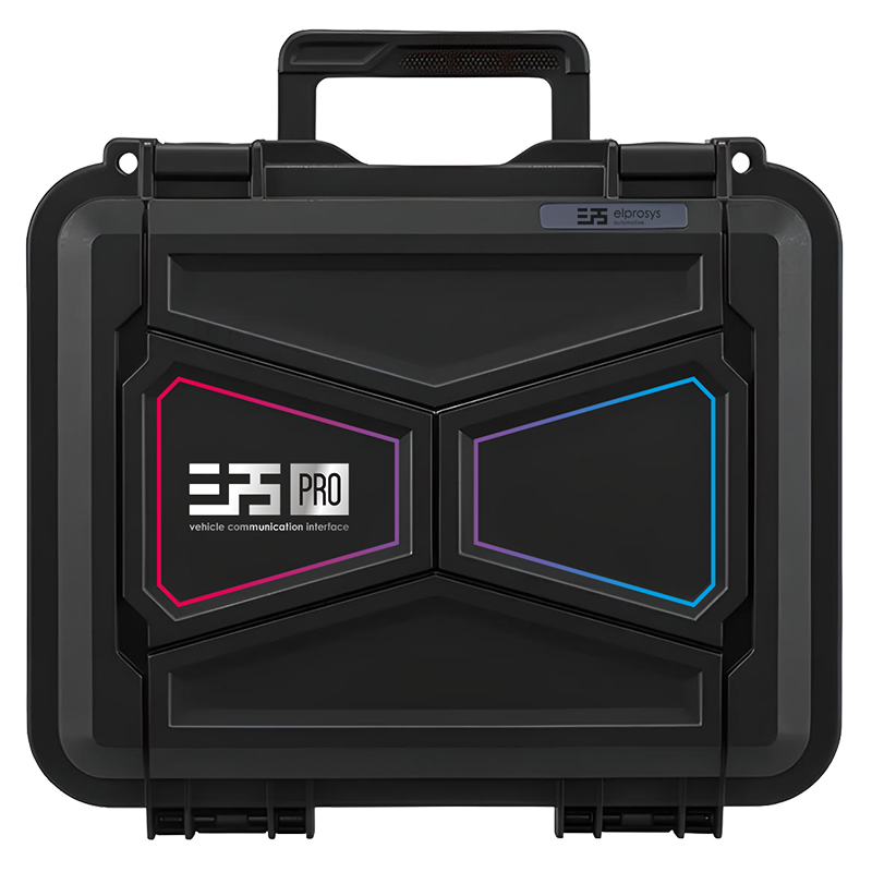
    Transport case

    Protection for storage and transport

  3. 03

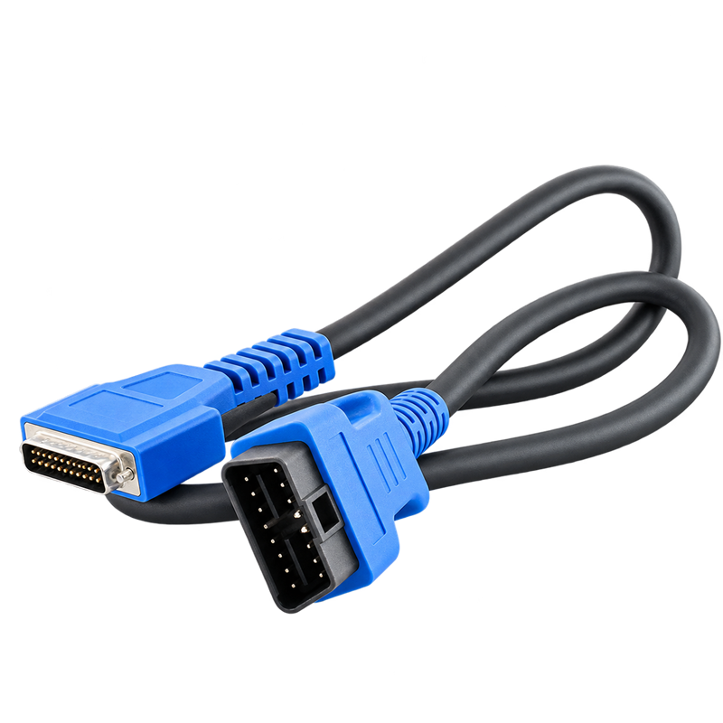
    D3 / OBDII cable

    Vehicle diagnostic connection via OBDII port

  4. 04

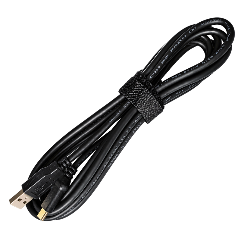
    USB cable

    Wired host connection
    USB-A - USB-C

  5. 05

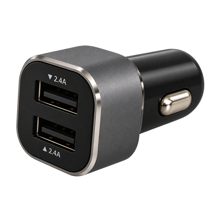
    Power adapter

    Adapter for the cigarette lighter socket

Next step

Continue with the software.

Explore the ELP Pass-Thru Link application or check OEM software for your vehicle brand.